Rack-scale AI systems such as Vera Rubin require data centers to manage more concentrated power demand, rapidly changing loads, and coordination between power and cooling. 800 VDC is one path in the evolution of power distribution: delivering direct current at a higher voltage reduces the current required for the same power, while the architecture determines where power conversion equipment is placed.
This shift affects how facilities allocate capacity, provide redundancy and expand. It also changes the delivery requirements for GPU colocation and dedicated compute services.
From Individual Servers to Rack-Scale Computing, the Unit of Power Planning Is Changing
As GPU systems become more concentrated, power increasingly needs to be planned by rack, row and cluster. Sufficient total facility capacity only means that resources are available upstream; power must still pass through every level of equipment to reach the computing systems reliably.
| System type | Power planning priorities | Common misconception |
|---|---|---|
| Multiple independent GPU servers | Server inputs, rack power distribution and simultaneous operating loads | Treating a server's rated power as the operating energy consumption of the entire facility. |
| Rack-scale computing systems such as GB200 NVL72 | Coordinating compute, interconnects, power supplies and liquid cooling within the rack | Treating rack-scale requirements as a purchase of ordinary rack space. |
| Vera Rubin and subsequent high-density architectures | Planning row-level power, conversion locations, load variation and expansion in advance | Assuming a platform roadmap means that every system uses the same power architecture. |
NVIDIA's 800 VDC roadmap includes both transition options for existing AC facilities and new-build architectures, allowing operators to choose an approach that fits their sites.
What Problems Does 800 VDC Address?
800 VDC is an innovation in power distribution architecture for high-density AI computing. Raising the distribution voltage reduces current at the same power level, easing space constraints for busbars, cables and connectors. Moving some power conversion equipment beside the rack or to row-level infrastructure frees space inside compute racks and supports expansion to higher-power systems. These changes also affect power distribution, redundancy and operating procedures. Overall energy savings still depend on converter efficiency, wiring, distribution distance and load.
Using P = V × I and ignoring losses, delivering the same 100 kW requires approximately 2,000 A at 50 V, compared with 125 A at 800 V. The higher voltage is used for distribution, with further step-down conversion inside the rack to the voltages required by GPUs and other components.
Market Approaches Range from AC Transitions to Row-Level and Facility-Level DC
Existing facilities and newly built AI data centers typically need different adoption paths. Retaining existing AC distribution and adding conversion equipment in selected areas enables phased deployment. Larger new-build projects may instead plan a DC architecture from the facility level.
NVIDIA's planned power racks, row power centers and DC power blocks move the conversion point from beside the rack to the row and facility levels. The diagram below compares what changes when conversion moves outside the compute rack; the table then summarizes the deployment approaches.
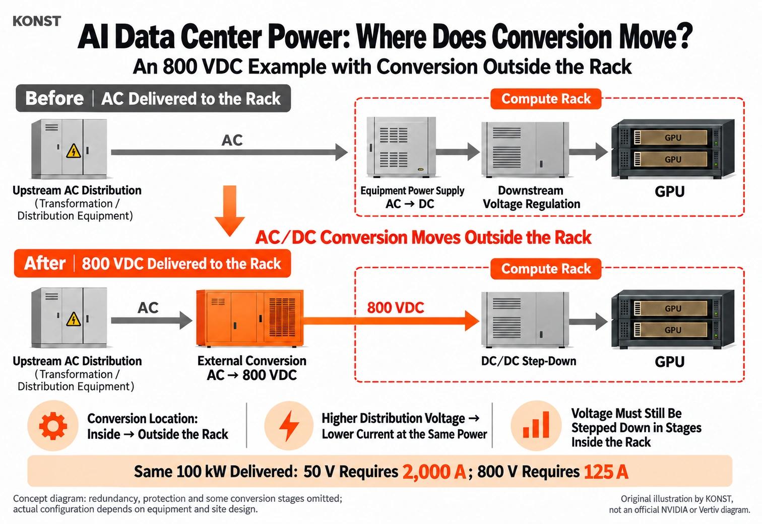
The dashed outlines show the same compute-rack boundary. Orange equipment and arrows illustrate AC/DC conversion moved outside the rack and the 800 VDC distribution path. The diagram is based on NVIDIA's power architecture and Vertiv's technical explanation.
| Approach | Power arrangement | Key assessment criteria |
|---|---|---|
| Existing AC distribution with conversion inside the equipment | Retain facility distribution, with equipment power supplies handling downstream conversion | Compatibility with the target system and sufficient capacity at the rack. |
| AC facility with a power rack or sidecar | Convert to 800 VDC close to the compute area | Space for conversion equipment, upstream AC headroom, maintenance isolation and downstream interfaces. |
| Row-level power | Shared distribution and conversion for a row or multiple racks | Failure impact, expansion methods and allocation of shared capacity. |
| Facility-level DC architecture | Convert further upstream and integrate distribution | New-build work, power and energy-storage controls, equipment supply and regulatory verification. |
Vertiv's sidecar architecture, Schneider Electric's GPU reference designs, and Delta's integration of power, energy storage and cooling illustrate how equipment vendors are moving from individual products toward complete power solutions.
How Power Distribution Changes Affect Facility Operations and Service Selection
When multiple racks share conversion equipment, operators must allocate capacity explicitly and define which racks are affected by an equipment failure or maintenance. DC distribution also requires appropriate protection, isolation and personnel procedures, while power, cooling and control systems need to undergo coordinated acceptance testing.
For businesses using GPU colocation, bare metal or dedicated clusters, these design choices ultimately affect available capacity, service interruptions and expansion conditions. The following criteria can help compare operating arrangements.
| Assessment area | What to confirm with the provider | Effect on the service choice |
|---|---|---|
| Sustained available capacity | Committed capacity per rack or cluster, load limits and usable capacity with redundancy accounted for | Confirm that compute remains usable under the agreed conditions. |
| Equipment and power interfaces | Target system models, input specifications and who provides conversion equipment | Avoid having to buy additional equipment or alter infrastructure after installation. |
| Faults and maintenance | Service impact and notification arrangements when a power path fails or equipment needs maintenance | Compare the downtime risk that is actually acceptable. |
| Cooling and controls | Responsibilities and coordinated acceptance testing for power, liquid cooling and monitoring | Check that the SLA does not cover only part of the system. |
| Expansion and billing | Whether capacity is installed, reserved or still planned, and when acceptance and billing begin | Distinguish available resources from future options and assess the cost of waiting. |
| Workload recovery | Who restarts nodes, restores scheduling and loads training checkpoints | Do not confuse facility power restoration time with application recovery time. |